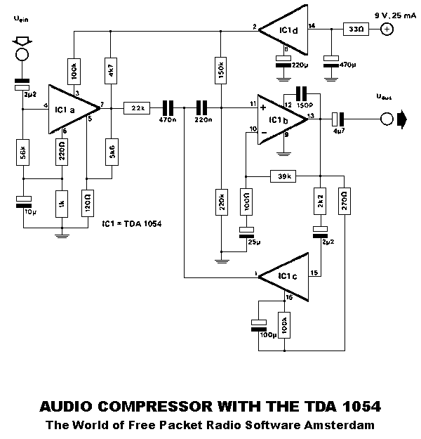
Audio Compressor Limiter Page 01
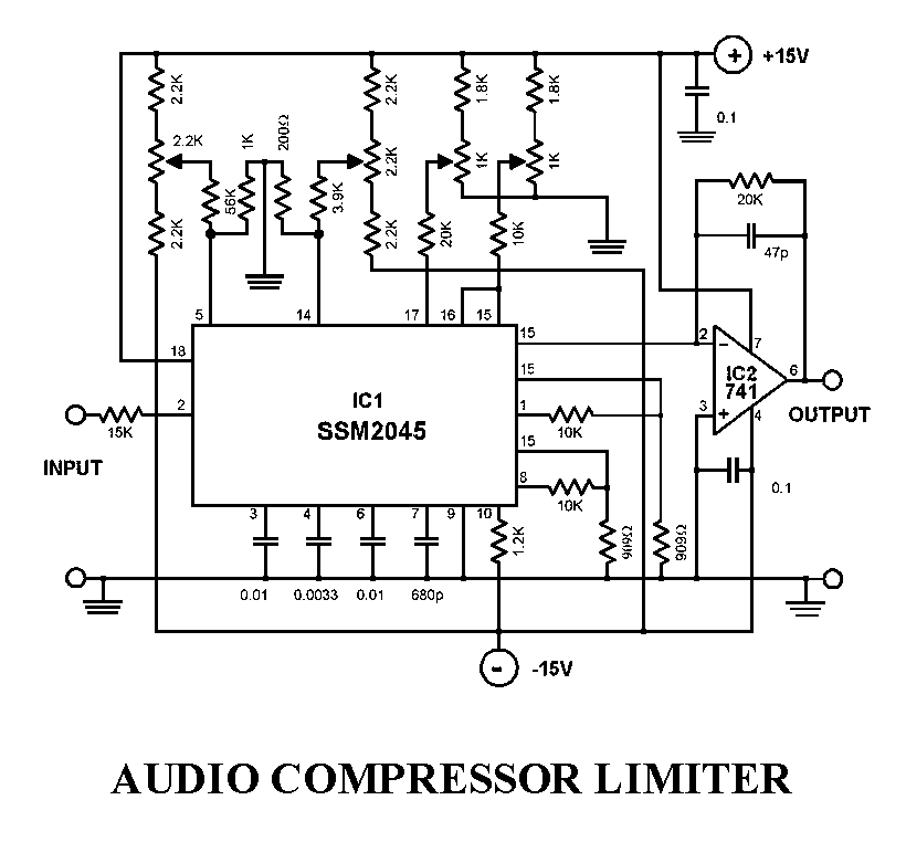
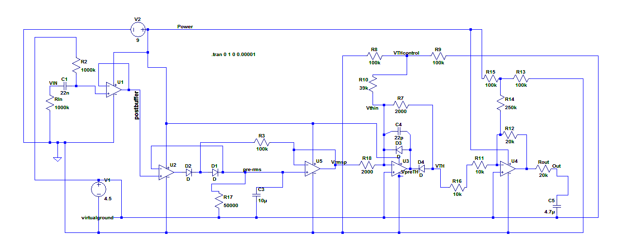
Here my schematic for Pro Audio Amplifier Limiter. The idea is using P-JFET with biased continuously to perform continues attenuation in the linear area, to perform like class A amplification but in opposite function as attenuation. As it is attenuated then it produce small signal voltage then it is amplified.

Audio Compressor Limiter Schematic AUDIO BARU
Audio Limiter GENERAL DESCRIPTION The NJM2761 is the audio limiter for speaker protection. The limit level is adjustable by external resistor. It is suitable for PC, potable audio and others. PACKAGE OUTLINE NJM2761RB2 NJM2761V FEATURES Wide Operating Voltage Variable Limit Level by external resistor Low Output Noise Bipolar Technology
StereoLimiter
ESP Project Pages - Audio Amp Power Limiter. Visit my other pages for more audio projects and articles. Elliott Sound Products: Project 53 : Audio Amp Output Power Limiter. Figure 2 - The Complete Limiter Circuit. The value of R3 must be selected based on the amplifier power. For a 100W amp, a value of 1.8k is about right, but it is likely.
Audio Peak Limiter Circuit
The limiter compressor circuit operates the audio gain around a fast attacking limiter in conjunction with a gentle AGC. action. Audio compression and output level are constant for input levels between - 12dBu and +24dBu. The limiter circuitry also includes selectable pre-emphasis. Some audio equipment, eg. CD players and computer
Audio Noise Limiter Full Circuit Diagram with Source Code
An audio limiter circuit is a device that helps control the recording level of audio. It works by attenuating the input signal when it reaches a certain threshold level. This helps prevent the output level from becoming too high and causing distortion. Hardware Required Circuit Diagram How Does an Audio Limiter Circuit Work?
Here Can You Find A Schematic of A Audio Compressor Limiter Compressor Limiter 02 of 06
Building DIY 1176 Compressor. The UREI 1176 Peak Limiter is a classic audio compressor designed by Bill Putnam, first built in 1967, making use of FETs and using them as a variable resistor to control the gain reduction in the circuit. The 1176 has been employed in countless recordings over the years and it is still used by almost every.
Audio limiter
41414 - Advertisement - Audio noise can be annoying, especially if you are trying to listen to a very weak radio station. Peaks of unwanted background noise completely swamp the broadcast signal, making it unintelligible. The audio noise limiter circuit presented here overcomes this problem by limiting the noise peaks.
LOW_DISTORTION_AUDIO_LIMITER Basic_Circuit Circuit Diagram
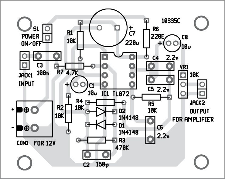
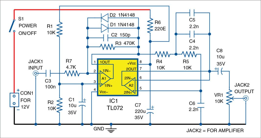
This audio peak limiter employs a FET as a variable resistance to attenuate the input signal according to a control voltage (CV). It offers unusually good performance with low cost and component count. A TL072 dual opamp (U1) provides the circuit gain and full wave peak detection.
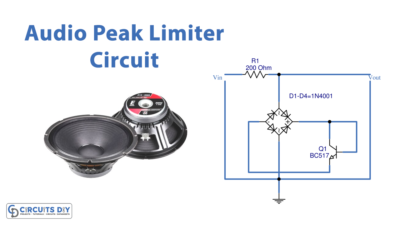
Audio Peak Limiter Circuit
Audio limiters can be used in a transmitter schematic or in any circuit you need a constant audio level. Audio limiter circuit schematic Audio limiter components R1 = 100K R2 = 1K R3 = 1M R4 = 68K R5 = 10K C1 = 10uF C2 = 680nF T1 = BFW11 T2 = BC173C IC = BA741 741 datasheet Share this: Tweet Share More Previous

Limiter circuitBased Audio OpAmp World Electricity
Audio Compressor Circuits and Schematics | ElectroSchematics Advertisement Audio Compressor Circuits and Schematics Browse through our collection of free DIY audio compressor circuits, projects, and schematics. Plus, find helpful diagrams, step-by-step instructions, and more. Audio Compression Amplifier /AGC Jim Keith - 12/21/2013
Stereo Limiter
It is basically a more straightforward way of implementing automatic gain control (AGC), though a limiter is not called an AGC circuit and for good reason—AGC uses feedback to ensure that the output signal always has a certain amplitude, whereas a limiter merely ensures that the output doesn't exceed a certain amplitude.
Audio Noise Limiter Full Circuit Diagram with Source Code
Unfortunately, I couldn't locate the article, yet luckily, the circuit is still available! This circuit is supposed to be wired at the mic ch. input before the mic preamp input buffer! Fig.1: INGÅNG=input , UTGÅNG= output. Fig.2; Green line = Dynamic Mic alone. Blue ine = Condenser Mic alone. Red line = Condenser + limiter in.
A Hard Audio Limiter
As with a peak measurement, the RMS value for a sinewave is obtained simply by scaling the rectified voltage, and in this case a meter would be adjusted to read 707mV with an input of 637mV. The average value of a sinewave is determined by. 2 × V (peak) / π = 0.6366 (0.637) for a 1V peak sinewave (707mV RMS) It is important to understand.

Upper/lower limiter circuit using op amplifier LM324
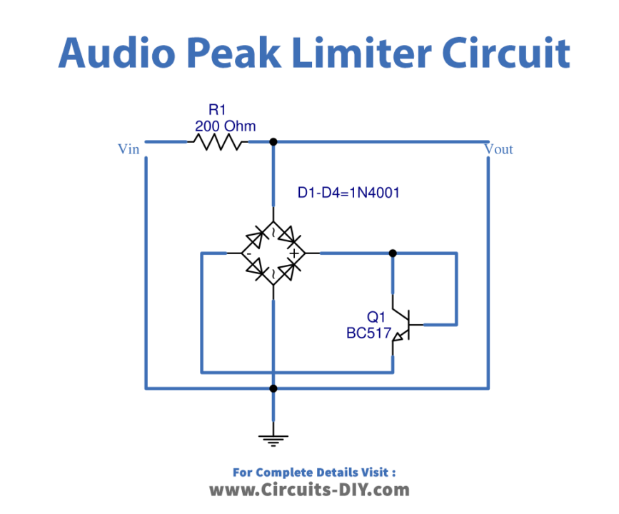
In electronics, a audio limiter is a circuit that allows signals below the specified input power to pass unaffected while weakening stronger signal peaks that exceed the strength of this input.
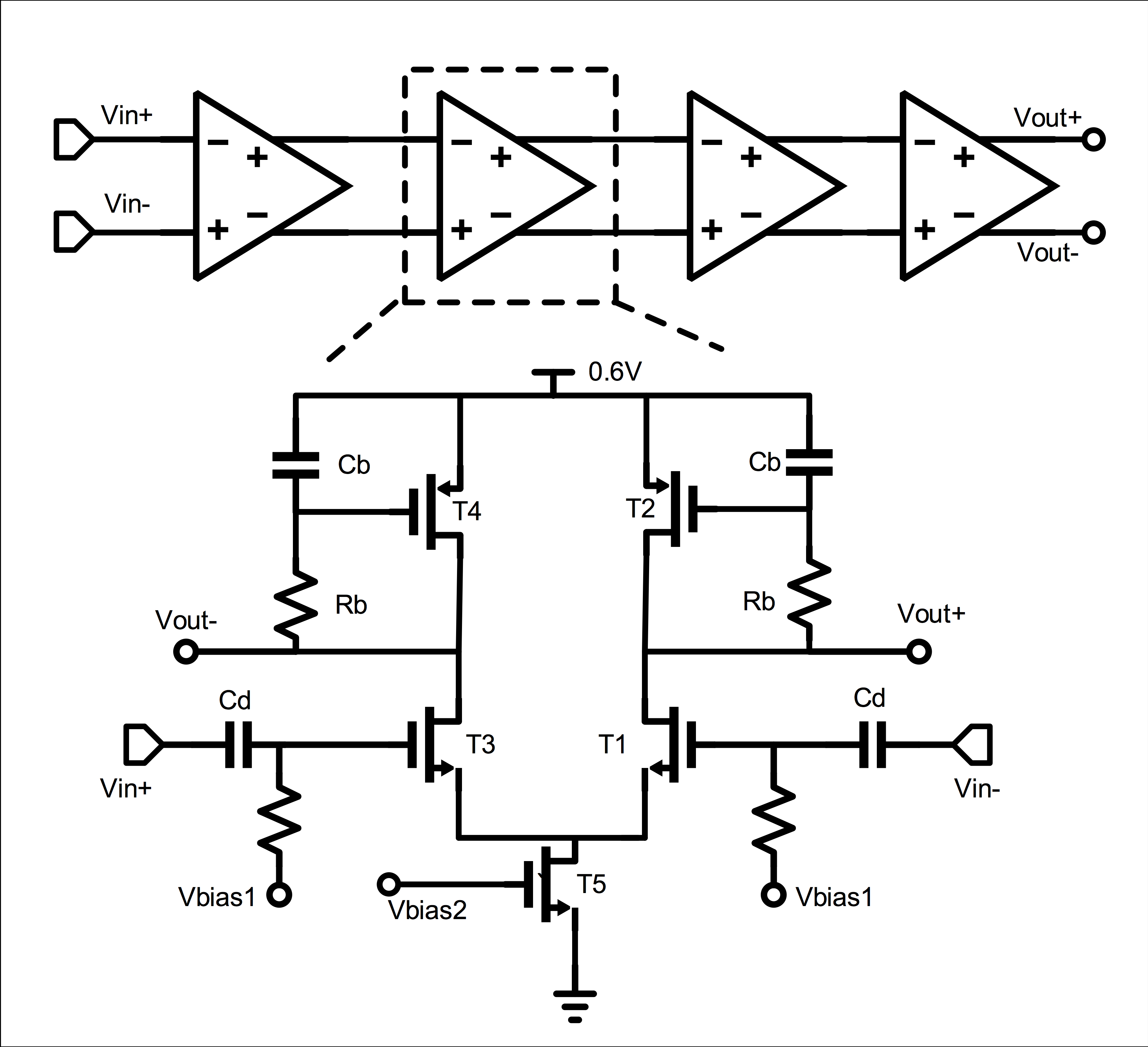
Fig.4 Simplified Schematic of Limiting Amplifier
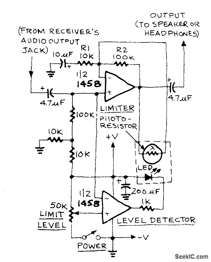
With audio limiter circuit the input signal is placed on an attenuator which can be created through R1 and PCC1. Usually PCC1 is within complete darkness and displays a really high resistance (generally a few megohms) leading to marginal failures with the attenuator.
Audio Compressor Circuit Diagram Audio Noise Limiter Full Circuit Diagram with Source Code
Schematic and Layout https://youtu.be/QvQnkpx2asw Aug 29,2020 6,491 views Simple audio limiter This limiter circuit use to avoid clips on a mid-power amp. It controll and decrease the input of amplifier by sensing the amplifier output 6491 8 0 5.75 (1) Published: Aug 29,2020 PCBWay Donate 10% cost To Author Add to cart
